NEMA Wiring Diagram Manual for Electrical Specialists
Nearly 70% of electrical breakdowns across installations are due to poor wiring practices. This fact accentuates the requirement of following set protocols, highlighting NEMA wiring schematics’ importance for electrical specialists. Through these schematics, wiring configurations that meet both performance productivity and optimal safety norms are presented.
The aim of this document is to equip electrical experts with deep understanding into NEMA standards. Emphasizing the value of correct electrical setups is vital. Through mastering these principles, technicians can drastically minimize the risk of accidents and guarantee they meet safety measures endorsed by Installation Parts Supply. Understanding of l14-30 plug wiring diagram is essential whether developing new systems or repairing existing ones, as it improves the capability to offer reliable and dependable electrical systems.
Essential Insights
- NEMA wiring schematics are vital for ensuring electrical security and conformity.
- Proper wiring techniques can decrease electrical malfunctions substantially.
- Grasping NEMA criteria enhances the efficiency of electrical arrangements.
- Installation Parts Supply promotes following safety standards in electrical tasks.
- NEMA schematics cover a variety of uses across different fields.
Understanding NEMA Standards and Their Significance
NEMA standards are pivotal in the electrical field, directing protection and functionality carefully. Crafted by the National Electrical Manufacturers Association, they define pivotal standards for designing, examining, and marking electrical equipment. Such measures guarantee uniformity and trustworthiness across all electrical installations, which is invaluable.
Identify the NEMA Norms?
NEMA classifications differ from grades 1 through 13. Every level specifies the criteria suitable for electrical devices to operate optimally. For instance, NEMA 1 delivers fundamental indoor security but lacks dust protection. On the other hand, NEMA 4 ensures appliances is watertight, a requirement for enduring substantial water exposure. Comprehending these designations is key in picking proper appliances.
How NEMA Criteria Matter for Electrical Security
The role of NEMA norms in ensuring electrical security is profound. They play a significant part in minimizing shock risks, apparatus failures, and fire hazards. Proper adherence to NEMA ratings enables devices to operate safely under particular surrounding conditions. For external usage, NEMA 3 ratings deliver protection against the environment, shielding the device from harsh conditions like downpour and blizzard conditions. In zones prone to explosions, ratings like NEMA 7, 8, and 9 are essential for maintaining protection.
Applications of NEMA Standards in Wiring Schematics
The implementation of NEMA standards in wiring drawings is vital for protected, optimal electrical systems. These diagrams make use of uniform symbols and formats originating from NEMA classifications, simplifying the comprehension of intricate electrical configurations. This standardizing is helpful. It encourages lucidity, consistency, and diminishes confusions, thus improving electrical security across residential and commercial landscapes.
NEMA Wiring Schematic Essentials
NEMA wiring schematics are vital for electrical experts, making complicated linkages transparent. They detail the junctions and components in different installations. By grasping the components, types, and symbols of NEMA schematics, technicians can enhance their work in setups and servicing.
Components of NEMA Wiring Diagrams
NEMA drawings include key components for particular electrical setups. You’ll see wiring endpoints, interfaces, and additional fixtures for secure linkages. Each piece guarantees energy is allocated efficiently, in accordance with safety protocols.
Categories of NEMA Wiring Diagrams
NEMA employs various diagrams, like linkage schematics and circuit designs. These schematics detail device relationships, while arrangements display energy distribution. Selecting the appropriate drawing facilitates problem solving and installation.
Typical Notations Used in NEMA Wiring Schematics
Notations in wiring drawings are crucial for unambiguous communication. They depict controls, circuits, and connectors. Recognizing these notations helps crews read schematics properly. Such practice ensures installations adhere to NEMA standards.
NEMA Wiring Diagram Attributes
For electrical specialists, understanding the fundamental elements of accurate electrical wiring schematics is essential. These drawings offer both lucidity and completeness, aligning configurations with NEMA norms. They demand accurate annotation and sizing to minimize deployment issues. Such practices promote a safer and highly efficient operational setting.
Essential Features of Accurate Electrical Wiring Diagrams
Accurate electrical wiring diagrams are indispensable in electrical projects. They embody important features such as:
- Clarity: Schematics must be simple, reducing the risk of misinterpretation.
- Thoroughness: They need to contain all essential parts, junctions, and electrical standards.
- Conformance: Following NEMA norms is non-negotiable for securing safety and operation.
- Detailed Labeling: Distinct annotations on each element are essential for comprehension and minimizing errors.
- Accurate Proportions: The proportions should mirror the actual setup to depict the arrangement correctly.
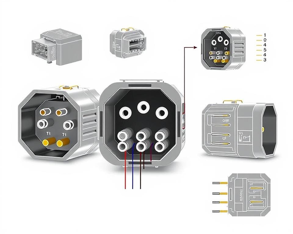
Understanding NEMA Connector Configuration
Grasping NEMA coupler configuration is critical for establishing correct junctions in electrical networks. Understanding of particular pin configurations maintains security and device performance. There exists a diversity of NEMA couplers, intended for distinct power levels and amperages, covering:
| Connector Model | Ampere Rating | Power Rating |
|---|---|---|
| L5-15 | 15A | 125V |
| L5-20 | 20A | 125V |
| L14-20 | 20A | 125/250V |
| L1430C | 30A | 125/250V |
| L620C | 20A | 250V |
| L1430C | 30A | 125/250V |
| L630R | 30A | 250V |
Comprehending NEMA coupler layouts is crucial for secure connections, enhancing effectiveness. It’s imperative to align couplers with equipment correctly using twist-lock or linear blade types, to dodge hazards.
NEMA Device Wiring
NEMA device wiring encompasses diverse arrangements for secure electrical appliance linkages. These rules ensure that equipment integrate safely, reducing hazard. Knowing the diverse NEMA equipment and their wiring is crucial for electricians.
Various Kinds of NEMA Appliances
NEMA organizes units by kind based on voltage levels and current requirements. Primary configurations are:
- 2-Pole, 2-Wire
- 2-Pole, 3-Wire with Grounding
- 3-Pole, 3-Wire
- 3-Pole 4-Wire Grounding
- 4-Pole, 4-Wire
- 4-Pole 5-Wire Grounding
These arrangements find use in residences and factories, supporting 125V, 208V, and 480V.
NEMA Outlet Wiring Explained
NEMA plug wiring changes to suit multiple energy requirements, with rotary-lock types providing secure interfaces in shaky environments. For instance, the L5-15 plug is rated for 15 amps, common in business sites, whereas the L14-20 is designed for 20 amps at 125/250 V.
The NEMA labeling convention aids in selecting the right plugs, emphasizing features like polarity and grounding. This precision guarantees that appliances operate securely.
NEMA Outlet Wiring Instructions
Correct wiring of NEMA outlets conforms to electrical regulations and safety norms. For example, L530R receptacles should be wired for 30 amperes at 125 voltage, with L630R variants for 250 V. Proper grounding is crucial to prevent electrical accidents.
Opting for accredited NEMA plugs and receptacles guarantees secure, regulation-compliant setups. It’s imperative to check authoritative guidelines when setting up.
NEMA Motor Wiring and Implementations
NEMA motor wiring is essential in electrical engineering, particularly for commercial use. Understanding how NEMA motor setup works secures that engines are integrated for optimal performance. Such devices, like single-phase and tri-phase variants, need proper wiring to function reliably and efficiently.
Overview of NEMA Motor Wiring
Grasping NEMA motor wiring requires knowledge of connections and arrangements. Most three-phase motors now support dual-voltage, meaning they can work on both low (208-230V) and high voltage levels (460V). Wiring at high voltage allows motors to draw less current than at low voltage. High voltage advantages comprise smaller wires for the power feed, a significant benefit for motors above 10 HP.
While both NEMA and IEC appliances are utilized in the sector, NEMA versions are usually bigger and more costly than IEC ones for below 100 HP uses. NEMA trips range from size 00 to 9, fit for diverse applications. A standard feature in NEMA trips is a Trip Class of 20, designed to trigger when a motor’s current exceeds 6x the Full Load Amperage (FLA) in 10 secs.
Selecting the Correct NEMA Motor Setup
Selecting the appropriate NEMA motor configuration affects overall performance and safety. A common three-wire control circuit utilizes three wires for a on/off pushbutton panel, allowing straightforward motor operation. Common three-phase arrangements include the 12 Lead Dual Voltage and 6 Lead, facilitating Wye and Delta arrangements.
IEC motor starters commonly feature phase failure detection, enhancing safety. They also include modifiable Trip Classes for customized protection in low power operations. Moreover, many variants have heat protection, critical for Single Phase and Dual Voltage setups.
| Configuration Type | Power Type | Amperage | Typical Use |
|---|---|---|---|
| 12 Lead Dual Voltage | Dual Voltage (208-230V / 460V) | Motor size dependent | Wye Start – Delta Run applications |
| 6 Lead | Single/Dual Voltage | Up to 32 amps | Wye or Delta connections |
| Single Phase | Single-level Voltage | Varies (1-5 amps adjustment) | Two Speed, Two Winding applications |
| Delta Connection | High Voltage | Variable | Current Transformers, multiple configurations |
Final Thoughts
Understanding NEMA wiring drawings and criteria is vital for electrical experts seeking to enhance their skills and comply with electrical safety norms. These standards not only ensure secure and effective electrical configurations but also avert risks stemming from improper wiring. As discussed, adhering to NEMA norms results in the augmented performance of diverse NEMA devices and setups.
For electricians, the availability of quality resources can significantly impact the result of their projects. Installation Parts Supply presents a vast array of wiring items in accordance with NEMA criteria. This empowers specialists to get critical components for meeting these important regulations. High-quality resources and profound understanding of NEMA wiring schematics significantly elevate project security and performance.
During electrical deployments, always place safety and accuracy as a priority. Becoming well-versed in NEMA standards delivers the understanding necessary for implementing industry standards accurately. This ensures that every electrical connection formed meets superior standards.
Frequently Asked Questions
What are NEMA wiring drawings?
NEMA wiring drawings showcase the configurations and connections of NEMA-standard electrical gadgets. They adhere to safety and performance criteria defined by the National Electrical Manufacturers Association.
What makes NEMA standards crucial for electrical protection?
NEMA criteria are fundamental to defining safety and functional standards for electrical gear. These guidelines assist electrical professionals minimize shock risks, operational errors, and burn dangers.
Which elements are essential in a NEMA wiring diagram?
Key elements in a NEMA wiring diagram consist of electrical layouts and junction blueprints. These diagrams also feature detailed markings and depict the electrical system’s diverse parts accurately for installations.
What types of NEMA wiring drawings exist?
Various NEMA wiring diagrams cater to various needs, including circuitry for power distribution and component interconnection schematics. Every design serves a unique role in electrical setups.
Which are the typical symbols employed in NEMA wiring schematics?
Typical symbols in these schematics depict toggles, circuit breakers, receptacles, and other elements. Use of these symbols facilitates unambiguous interaction and correct understanding of wiring schematics.
What are the key characteristics of accurate electrical wiring diagrams?
Correctness in electrical wiring schematics is characterized by their clarity, comprehensiveness, and explicit annotation. They must align with NEMA standards to avoid errors in deployment.
What is a NEMA connector pinout?
A NEMA connector configuration outlines electrical connections at a connector, showing distinct pin roles. This ensures secure and efficient connections in electrical setups.
Which are the various kinds of NEMA devices?
NEMA units include various electrical outlets and couplers, like plugs and sockets. They are engineered for diverse current and power criteria to meet unique application requirements.
In what way is NEMA plug wiring set up?
NEMA plug wiring depends on particular ampere and power needs, following safety standards and electrical codes for various electrical setups.
Identify the recommendations are there for NEMA outlet wiring?
Recommendations for connecting NEMA outlets emphasize complying with electrical codes, guaranteeing proper charge alignment, and picking appropriate gauge sizes. This ensures both safety and operation in electrical setups.
Describe how to wire a NEMA motor efficiently?
To set up a NEMA motor, one must comprehend its particular single-phase or three-phase arrangement. Opting for the correct wiring approach is essential, along with practicing electrical safety for maximum motor efficiency.
What must be taken into account when selecting a NEMA motor setup?
Selecting a NEMA motor setup requires an analysis of the application’s power needs and operational characteristics. It’s also crucial to confirm suitability with existing equipment for assured efficiency and safety.